
Drone Roof Inspection Report
Unmanned Aerial Vehicle visual survey of a 1930s semi-detached property with loft conversion, North London.
Methodology & Approach
This report has been prepared by North London Drone Surveys following a UAV (unmanned aerial vehicle) inspection of the property detailed on the cover sheet. All operations were conducted under the operator’s commercial CAA permissions in compliance with the Air Navigation Order 2016 and UK CAA Regulation (EU) 2019/947 as retained in UK law.
Drone inspection provides a comprehensive, high-resolution photographic and video record of all visible roof elements — including pitched slopes, flat membrane sections, hip and ridge details, chimney stacks, flashings, gutters, and abutments — without the need for scaffolding, ladders, or access platforms. Where a defect is identified, the relevant imagery is presented within this report alongside a technical description and recommended remedial action.
Survey Methodology
- High-altitude nadir pass (20–40 m) to establish overall roof geometry and drainage falls.
- Compass-point oblique passes to capture all elevations and roof slopes in context.
- Close-proximity detailed passes (3–8 m) targeting specific defects, junctions, flashings, and areas of concern.
- 4K continuous video recorded throughout; 48 MP stills captured at each identified defect.
- All imagery geo-tagged and time-stamped; annotated where required for client clarity.
Grading System
Each defect identified in this report is assigned a condition grade on the following scale:
| A | Good — No action required; within expected serviceable condition. |
| B | Satisfactory — Minor wear; monitor at next inspection. |
| C | Fair — Remedial works recommended within 12 months. |
| D | Poor — Remedial works required within 3–6 months. |
| E | Critical — Urgent action required; risk of water ingress or safety hazard. |
Limitations
This inspection is visual only and is subject to prevailing weather and lighting conditions. It does not assess structural integrity, internal dampness, thermal performance, or any defects concealed beneath roof coverings. Where the findings of this report indicate a need for further investigation, a roofing contractor or structural engineer should be engaged to inspect the relevant area at roof level before works are tendered or commenced.
Your property · from £179
Want this level of detail for your roof?
Every survey follows this same methodology — CAA-registered pilot, annotated 4K imagery, and a graded defect report delivered within 24 hours.
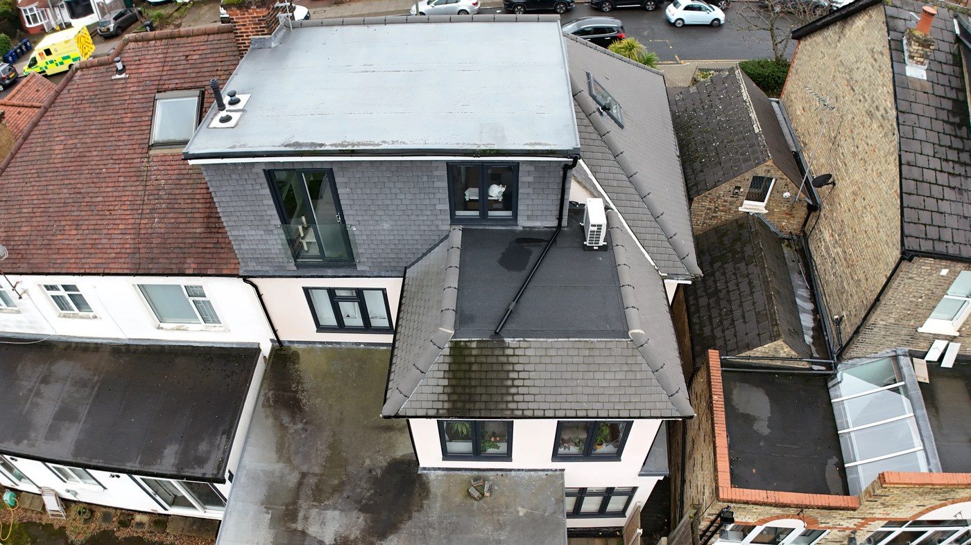
Property & Roof Overview
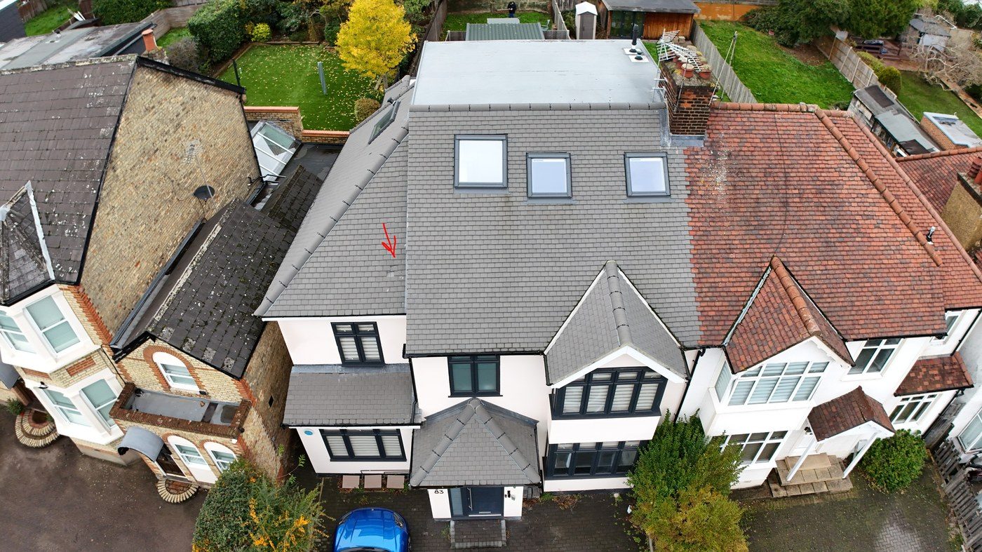
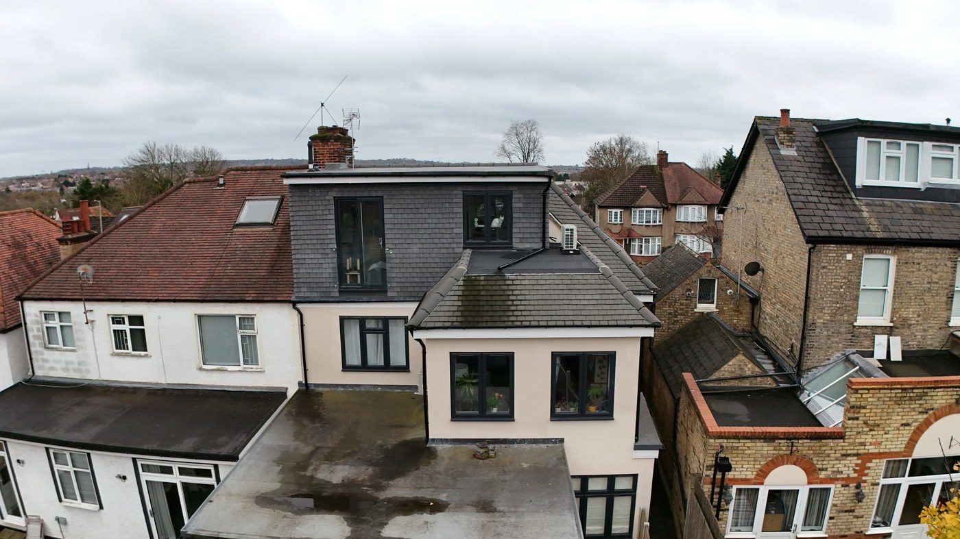
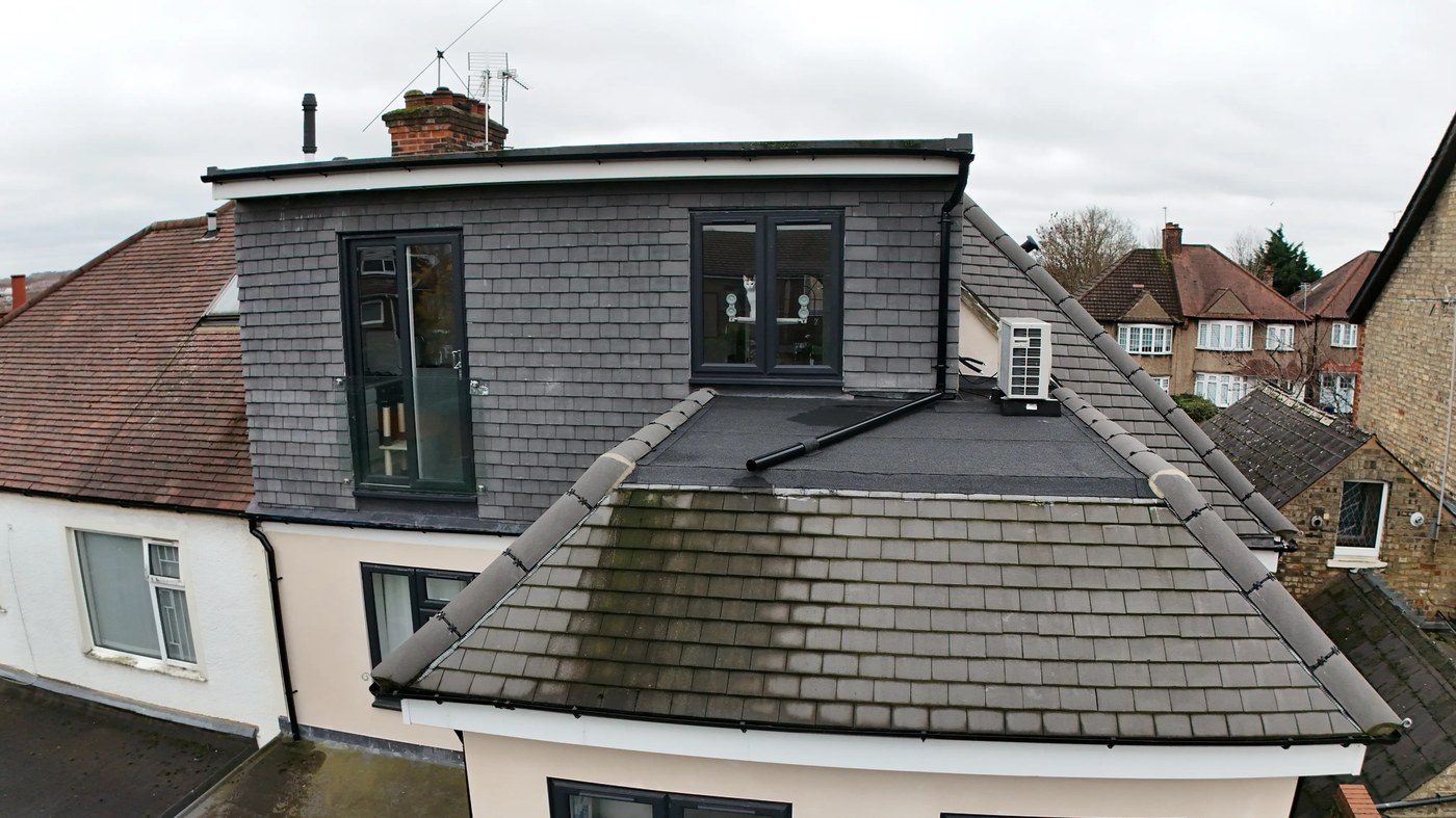
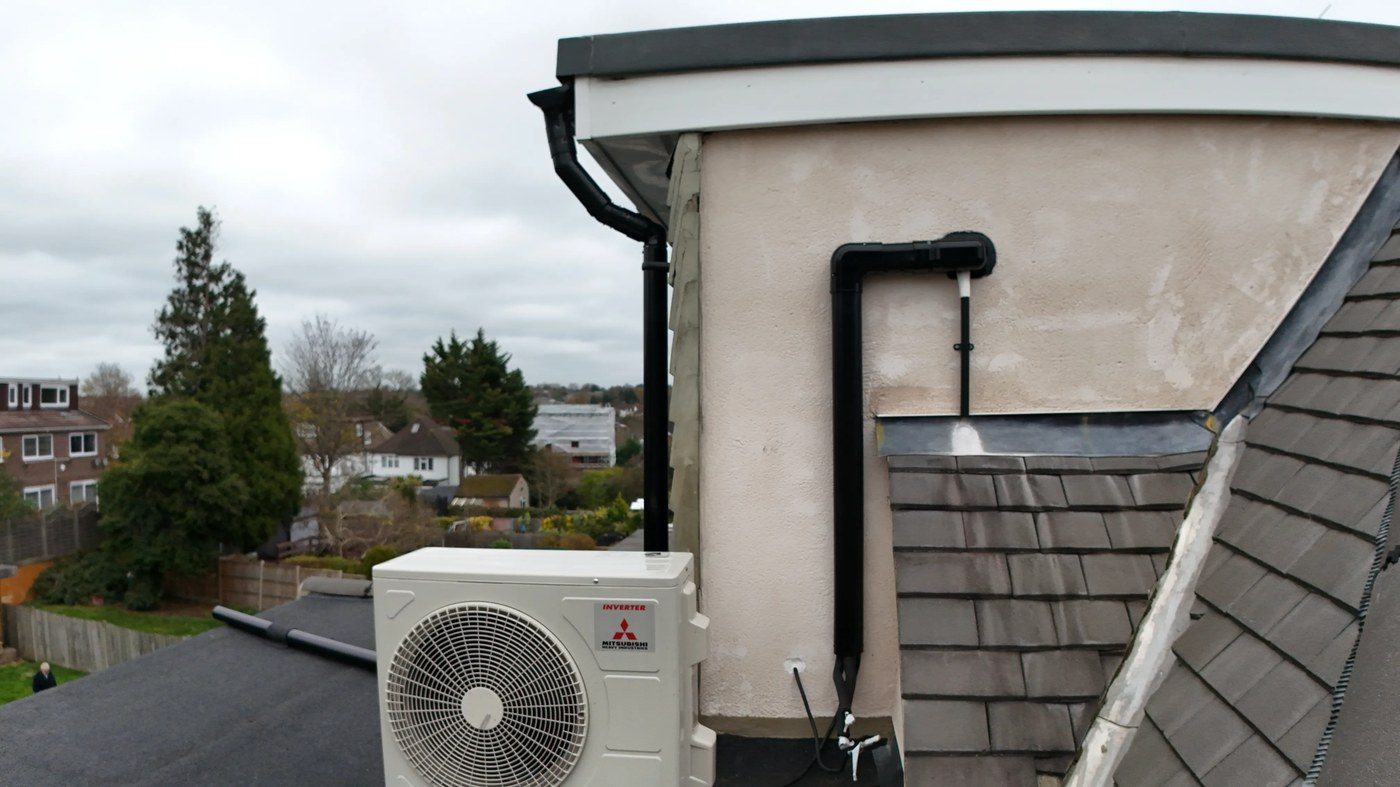
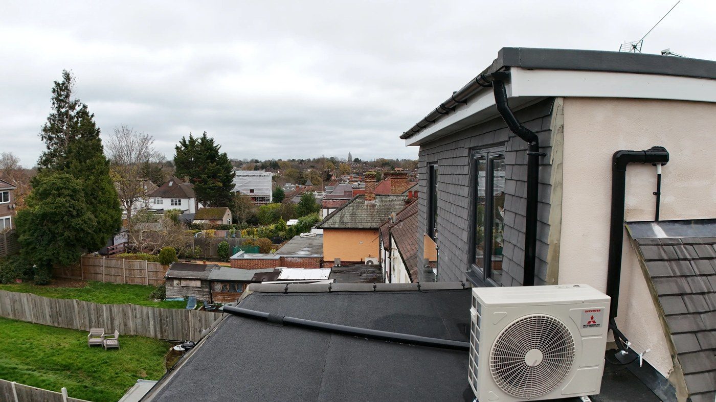
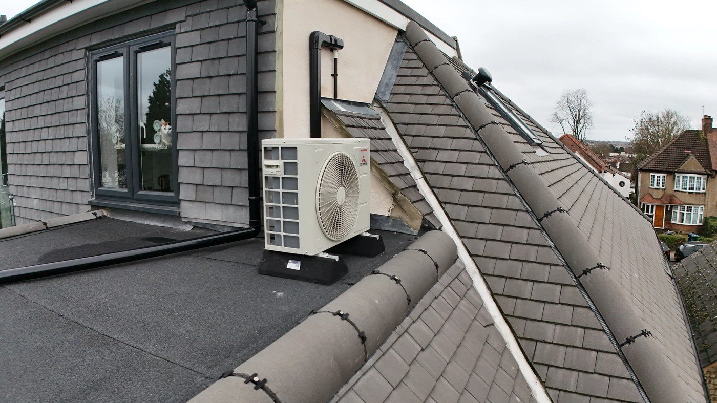
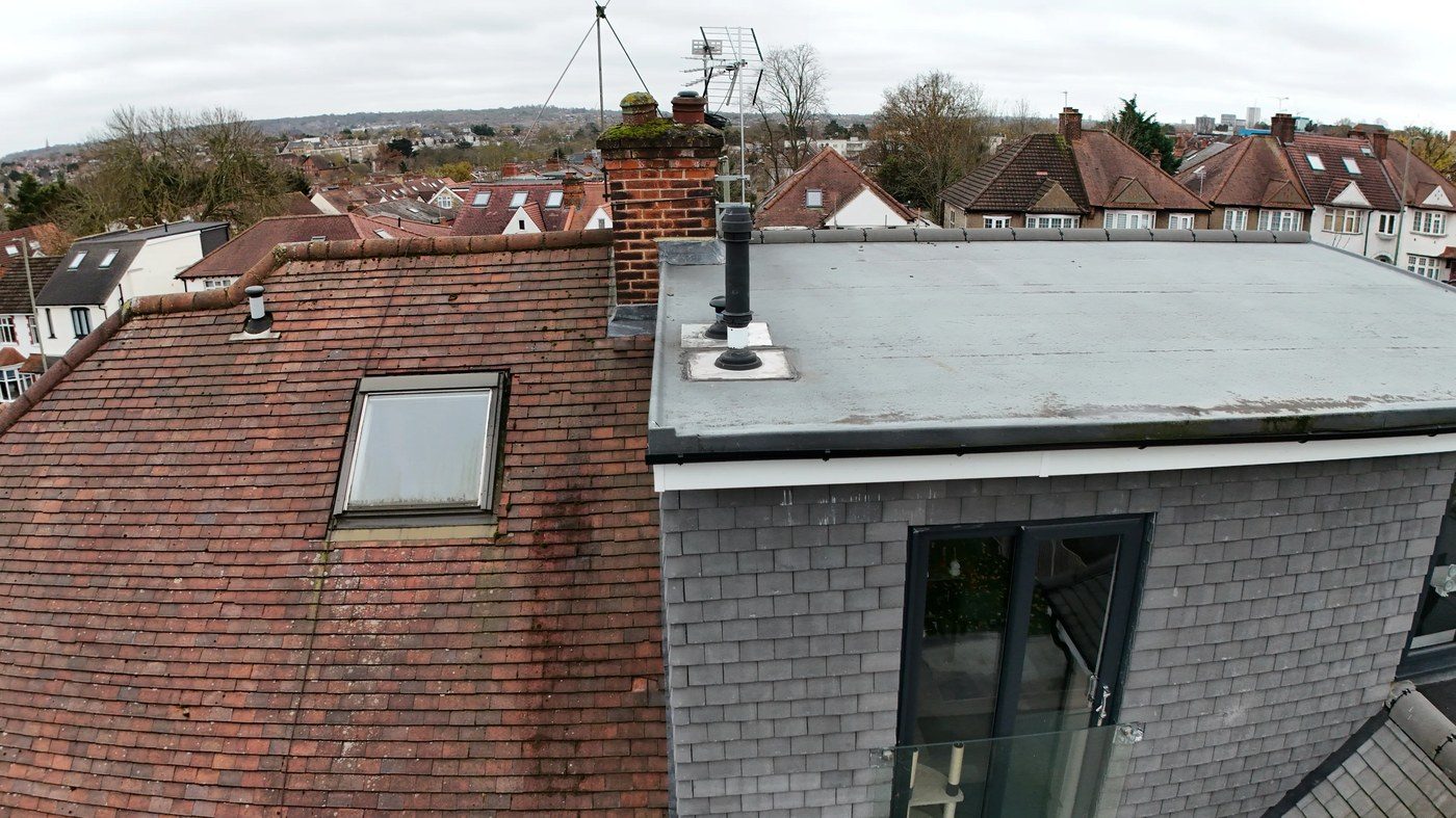
The property inspected is a two-storey semi-detached dwelling of 1930s construction in North London, which has undergone a substantial loft conversion, creating a third storey with dormer structure and flat membrane roof. The principal pitched roof is covered with modern grey concrete/composite slate-effect interlocking tiles installed as part of the loft conversion works. The dormer structure features a flat mineral-surfaced felt (torch-on) roof deck with a curved swept hip perimeter finished in concrete bonnet-type hip tiles mechanically fixed with dry-fix clips. A Mitsubishi air source heat pump (ASHP) is installed on the flat roof deck.
The adjacent neighbour’s property (left elevation) retains the original 1930s pitched roof finished in darker clay/concrete plain tiles with evidence of significant moss and lichen colonisation. A separate chimney stack serving the main property and/or the adjoining property is also within the survey scope.


| Roof Element | Condition | Grade |
|---|---|---|
| Main pitched slate-effect tile roof | Fair — one defect identified | C |
| Flat felt membrane roof (dormer deck) | Poor — ponding & drainage issues | D |
| Lead flashing at dormer abutment | Poor — not fully dressed | D |
| Hip tiles & dry-fix bedding | Fair — bedding concerns | C |
| Tile verge cement / pointing | Fair — mortar inadequate | C |
| Chimney stack | Poor — vegetation established | D |
| Moss & lichen growth | Significant on neighbouring elements | C |
| Gutters & downpipes | Generally satisfactory | B |
Eight Defects, Graded & Documented
Each defect is presented with the drone imagery used to identify it, a technical description of the condition observed, the potential consequences if unaddressed, and the recommended remedial works.
Slipped Roof Tile — Main Pitched Elevation

During the initial high-altitude nadir pass over the property, a slipped tile was identified on the front elevation of the main pitched roof, as annotated by the red arrow marker in the drone imagery. The tile has displaced downward from its correct interlocking position, partially exposing the course beneath and creating an open gap through which wind-driven rainfall can penetrate to the roofing underlay and potentially to the roof structure below.
The main pitched roof is covered in modern grey concrete or composite slate-effect interlocking tiles, which rely on mechanical interlock between adjacent units rather than traditional mortar bedding. Individual tile displacement of this type is typically caused by: failure of the mechanical fixing (nail or clip) holding the tile to the batten; impact damage from a falling object or foot traffic; or thermal/wind cycling causing the interlocking nib to work free over time.
Potential Consequences if Unaddressed
- Rainfall penetration through the displaced tile position will saturate the roofing underlay beneath; in the event the underlay is degraded, water will reach the roof timbers and insulation.
- A displaced tile represents a wind uplift risk — once lifted from its seating, the tile may become dislodged entirely in a storm event, creating a falling hazard.
- Adjacent tiles may progressively shift as the structural integrity of the course is compromised.
Recommended Remedial Works
- Engage a qualified roofer to access the tile position (scaffold or cherry picker) and re-seat the displaced tile, ensuring the interlocking nib engages correctly with the tile below.
- The fixing to the tile batten should be inspected and renewed — specify stainless steel or aluminium nails in accordance with BS 5534:2014+A2:2018.
- Inspect the three to four tiles immediately surrounding the slipped unit for similar movement; replace any tile where the nib or fixing is found to be compromised.
- Inspect the roofing underlay below the affected position from the loft space for any evidence of water ingress or moisture on the timbers.
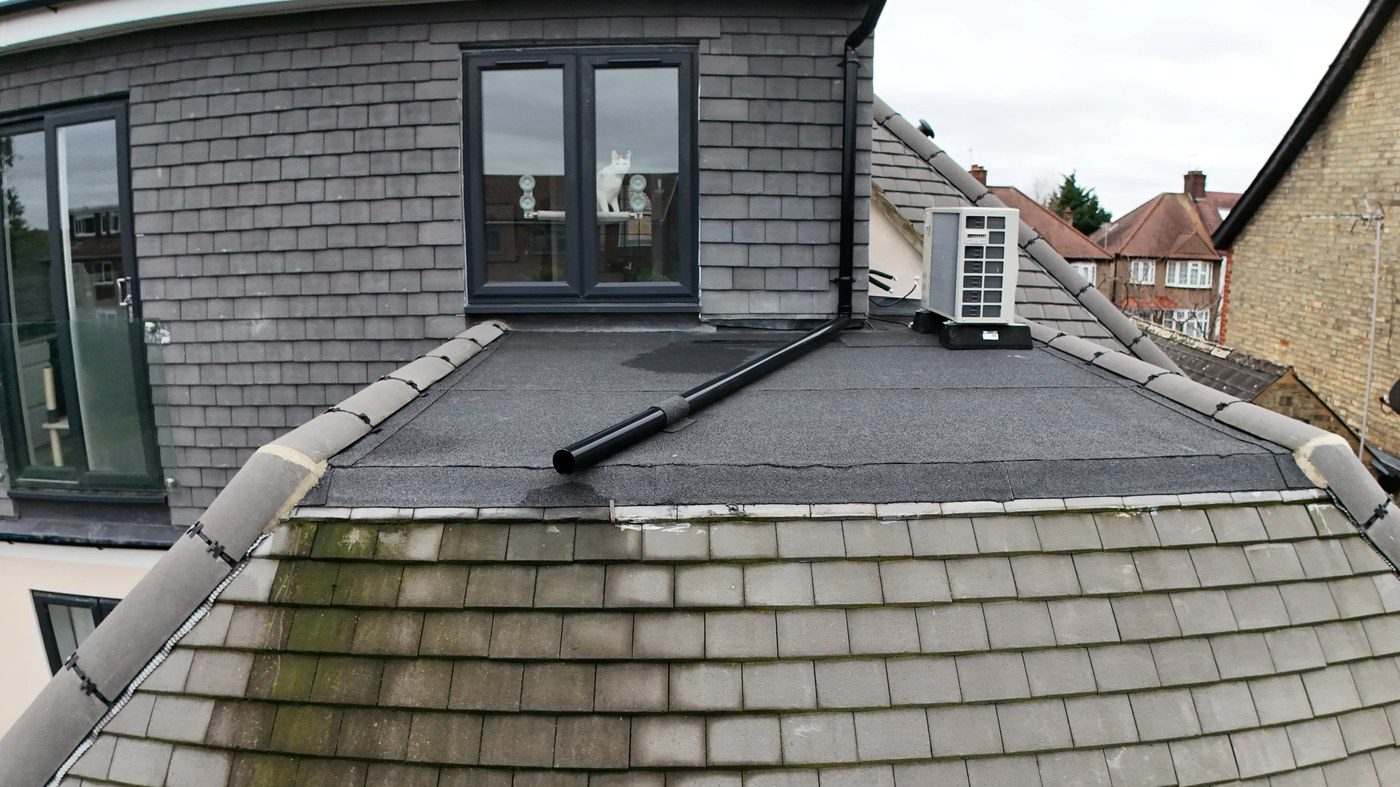
Ponding Water on Flat Felt Membrane Roof
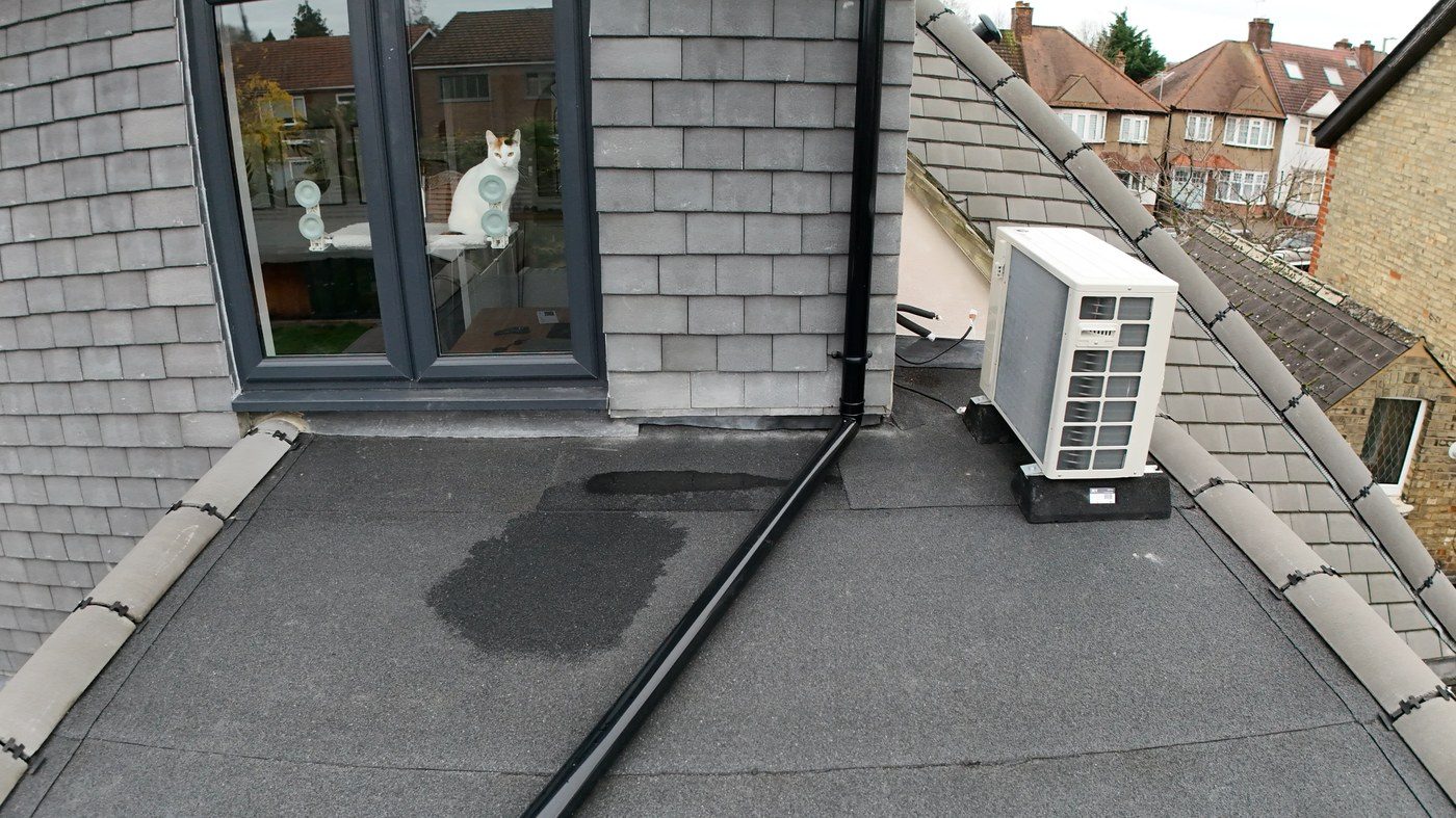
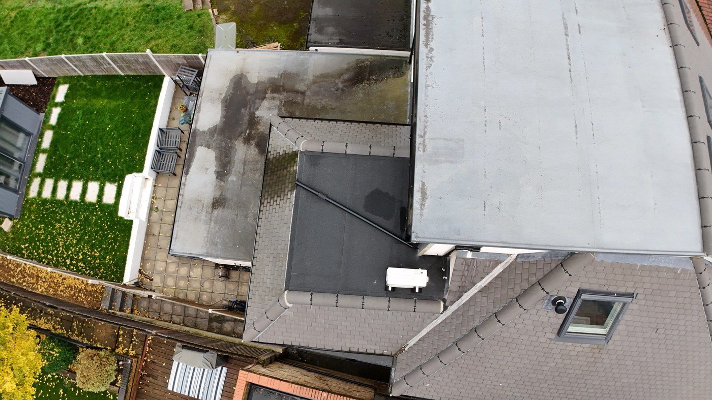
The flat roof deck covering the loft conversion dormer structure is finished in a mineral-surfaced torch-on felt (cap sheet) system. During the inspection, a substantial area of standing water (ponding) was recorded in the lower central portion of the roof deck. The water patch is clearly visible in the close-proximity drone imagery (Fig. 3.2a) and the staining pattern visible in the overhead shot (Fig. 3.2b) indicates that this is a recurrent and persistent condition, not an isolated post-rainfall occurrence.
UK Building Regulations Approved Document H and BS 6229:2018 (Flat Roofs with Continuously Supported Flexible Waterproof Coverings) require that flat roofs are designed and constructed to achieve a minimum drainage fall of 1:80, with a design fall of 1:40 recommended to allow for construction tolerances and long-term deflection. The pooling observed suggests the current falls are below this minimum, indicating either: a design/installation deficiency in the original loft conversion works; subsequent deflection of the roof deck due to loading (the ASHP unit) or structural movement; or a blocked/partially obstructed outlet.
Potential Consequences if Unaddressed
- Prolonged standing water accelerates UV degradation of the mineral felt cap sheet, breaking down the bituminous binder and leading to surface cracking and eventual membrane failure.
- Water retention creates hydrostatic pressure on any lap joints or details in the membrane, increasing the risk of water finding a path through to the roof deck below.
- The weight of retained water (1 litre = 1 kg/m²) adds to the structural load on the roof joists and may exceed the design load if ponding is extensive.
- Freeze-thaw cycling in winter months causes standing water to expand as ice, accelerating membrane deterioration.
Recommended Remedial Works
- Inspect and clear the flat roof outlet/drain immediately, and confirm the downpipe below is unobstructed at all levels.
- If clearing the outlet does not resolve the ponding, a flat roofing specialist should be engaged to assess the current falls across the deck using a spirit level or digital level.
- Where falls are confirmed to be deficient, a tapered insulation overlay system can be installed over the existing membrane to create the correct minimum 1:80 fall without structural alteration — the new insulation would then receive a new cap sheet membrane.
- If the existing membrane is found to have lap joint failures, blistering, or cracking in addition to the drainage issue, a full membrane replacement should be considered.
- Ensure the ASHP unit base frame is not obstructing the natural drainage path across the deck.
Lead Flashing Not Fully Dressed — Dormer Wall/Roof Abutment
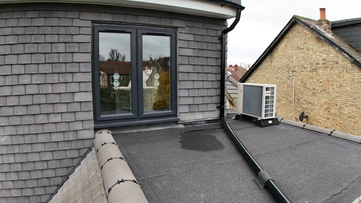
At the junction between the slate-clad dormer wall and the flat membrane roof deck, the lead cover flashing has not been fully dressed (pressed and formed) down onto the surface of the membrane. A correctly installed lead cover flashing at this type of abutment should be stepped or wedge-fixed into a mortar or structural chase in the wall above, with the lower skirt of the lead dressed flat onto the roof membrane surface and then sealed at the edge with a compatible sealant or the membrane lap turned up and bonded over the flashing tail.
The drone imagery clearly shows the lead flashing standing proud of the roof membrane surface — the flashing tail has not been worked down to make contact with the membrane, leaving a void behind it. This junction is a primary water ingress point: wind-driven rainfall will be driven under the raised flashing tail and onto the roof deck at the wall/roof junction, which is one of the most moisture-vulnerable details on any flat roof.
Potential Consequences if Unaddressed
- Wind-driven rain will be forced beneath the undressed flashing tail with each rainfall event, directing water onto the roof deck at the wall base and potentially into the wall construction.
- Water tracking behind the flashing will saturate the bottom course of slate cladding and the wall construction behind it, leading to damp penetration into the dormer structure.
- If water tracks down the wall cavity or behind the roof deck edge, it may enter the room below the dormer, causing internal damage to plasterwork and insulation.
Recommended Remedial Works
- The lead flashing should be re-worked by a plumber or qualified lead worker: the existing lead should be gently warmed if required and dressed flat onto the membrane surface using a bossing mallet and dresser tool.
- The base of the flashing should be bonded to the membrane using a compatible lead-to-felt adhesive or the membrane upstand turned over the flashing tail and torched/bonded in position.
- The top chase/fixing of the flashing into the wall above should be inspected — ensure it is correctly wedged and pointed with a flexible sealant or mortar.
- On completion, the junction should be tested with a low-pressure water test before scaffolding or access equipment is removed.
Poor Cement Mortar to Tile Verge / Wall Abutment
Where the main tile field meets the rendered dormer wall at the verge, the cement mortar pointing that seals the tile edge to the wall face is visibly inadequate. The drone inspection reveals thin, cracked, or in places entirely absent mortar at this junction. On a correctly detailed tile-to-wall verge, the mortar should be applied in two stages: a bed of mortar to support and align the tile at the correct overhang, followed by a pointing fillet that is weathered (angled away from the wall) to direct water away from the junction.
The defect is consistent with a verge that was originally mortared but has experienced significant thermal movement cracking and/or was not correctly formed at the time of the loft conversion works. This is a common finding on relatively new builds where OPC (ordinary Portland cement) mortar has been used without adequate flexibility additives — such mortar is prone to shrinkage cracking within the first few years.
Potential Consequences if Unaddressed
- Open joints at the tile verge allow wind-driven rainfall to penetrate behind the tile edge and onto the underlay, potentially reaching the roof timbers and insulation layer beneath.
- Without mortar support, the tile edge overhang becomes vulnerable to wind uplift, particularly in exposed positions.
- Water tracking behind the render finish at the dormer wall base may cause delamination of the render and damp penetration into the wall construction.
Recommended Remedial Works
- Rake out all existing cracked or loose mortar along the verge and tile-to-wall junction.
- Re-point using a flexible mortar compound — specify a BS EN 998-1 compliant pointing mortar with a polymer modification (e.g. an NHL 3.5 mix or a proprietary flexible tile pointing compound) rather than a straight OPC sand mix.
- Alternatively, a proprietary dry-fix verge clip system can be installed to the tile edge, eliminating the need for mortar bedding at the verge entirely and providing a more durable, BS 5534:2014-compliant solution.
- Where the render at the dormer wall base shows any signs of blowing or delamination, hack off and re-render affected areas after the verge repair is complete.
Found on a standard North London semi-detached
These defects are more common than you might think.
Eight issues were identified on this property — several invisible from ground level. A drone survey costs a fraction of the repairs they prevent.
Chimney Stack — Vegetation Growth & Flaunching Deterioration
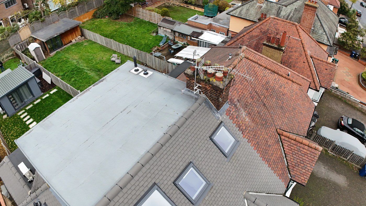
The chimney stack visible within the survey area exhibits a significant level of vegetation growth at its head — most clearly visible in the overhead drone image (Fig. 3.5a). Plant matter, including what appears to be self-seeded vegetation and dense moss, has established itself at the base of the chimney pot and across the flaunching (the sloped mortar collar that surrounds and seals the pot base). This is an unambiguous indicator that the flaunching mortar has cracked and opened to a degree that allows soil, moisture, and seed matter to accumulate.
The establishment of vegetation roots within masonry mortar causes progressive opening of joints through root action. The freeze-thaw cycle then widens these voids further each winter. Open joints at the chimney head allow direct water entry into the masonry, which can track down inside the stack and emerge through the chimney breast within the property. A blocked or partially obstructed chimney pot also presents a risk if the flue is in active use, as combustion gases may not vent correctly.
Potential Consequences if Unaddressed
- Root action from established vegetation will progressively open mortar joints in the upper brickwork courses, ultimately causing individual brick faces to spall and the stack to become structurally unsound.
- Water ingress through the failed flaunching will track down the chimney internally, causing damp staining to the chimney breast on internal walls and potentially saturating the chimney breast insulation.
- Debris from the vegetation may partially block the flue — if the chimney serves an active flue or wood-burning appliance, this is a fire and gas safety risk requiring immediate attention.
- Falling masonry from a deteriorated stack head is a safety hazard to occupants and neighbours.
Recommended Remedial Works
- Arrange scaffold access to the chimney head for a thorough close-range inspection.
- Remove all vegetation growth carefully, taking care to extract root matter from open joints.
- Rake out all open, cracked, or loose mortar joints in the upper stack courses and repoint using NHL 3.5 natural hydraulic lime mortar, appropriate for the exposure zone.
- Hack off the existing cracked flaunching in its entirety and rebuild using a flexible flaunching compound or a 3:1 sharp sand/OPC mix with the addition of a polymer SBR admixture; ensure the slope angle is at least 45° and the mortar is worked tightly around the pot base.
- If the flue is in active use, arrange a CCTV internal flue survey and sweep before relighting.
Swept Hip Tile Condition — Bedding and Foam Filler
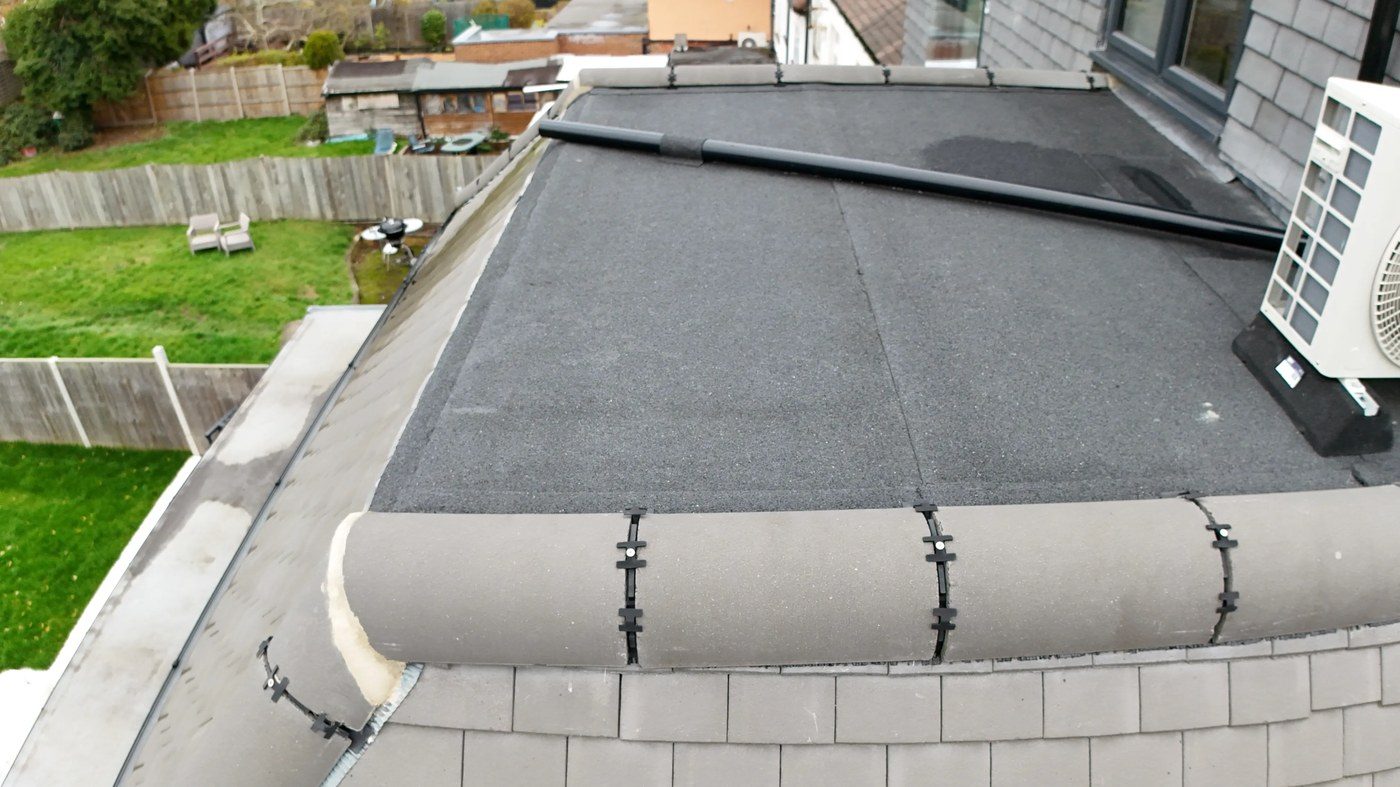
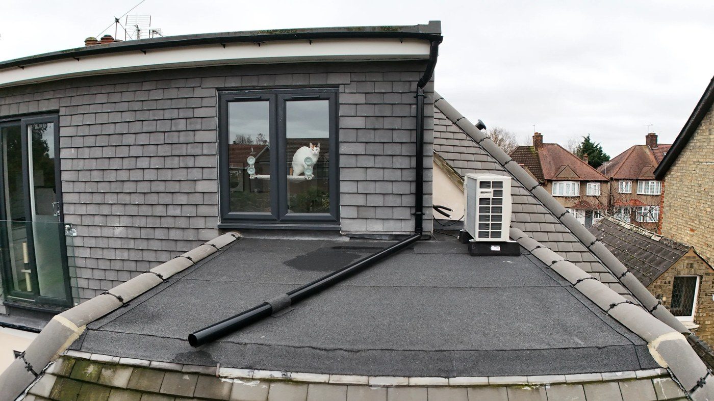
The swept hip perimeter of the loft conversion dormer is finished with concrete bonnet-type hip tiles, which appear to be mechanically fixed using proprietary dry-fix hip clip fixings — visible as small dark clips at each tile junction. This is an appropriate installation method consistent with BS 5534:2014+A2:2018, which requires mechanical fixing for all hip tiles.
However, at the eaves end of the hip tile run, the drone imagery reveals the presence of pale-coloured foam or foam-filler material in the gap between the bottom hip tile and the adjacent roof tile course. The use of expanding foam as a gap filler in roofing is a non-standard approach that is not recommended by any UK roofing standards. Expanding foam is not UV-stable, degrades over time, absorbs moisture, and does not provide a durable weathertight seal. Its presence suggests either an improvised repair or a shortcut taken during the original installation rather than a proper close-cut tile or mortar closure at the eaves/hip junction.
Additionally, early-stage moss growth is observed on the lower hip tile courses (Fig. 3.6b), which if left untreated will progress to the same level of colonisation seen on the neighbouring property’s roof.
Potential Consequences if Unaddressed
- Foam filler at the hip/eaves junction will degrade with UV exposure and thermal cycling, eventually crumbling away and leaving an open gap at the base of the hip tile run.
- Water entering the open hip/eaves junction can track beneath the hip tiles and onto the felt or membrane beneath.
- Moss growth on hip tiles will accelerate if left untreated, leading to root penetration and frost damage to the tile face over successive winters.
Recommended Remedial Works
- Remove the expanding foam material from the hip/eaves junction and replace with a correctly cut close-mitred tile piece or a proprietary eaves/hip closure unit appropriate to the tile profile.
- If the gap is too large for a tile closure, a lead soaker or Code 4 lead saddle piece should be formed and dressed into the junction in place of the foam.
- Apply a suitable biocide treatment to the hip tiles showing early moss growth, following manufacturer guidance; re-treat at the recommended interval.
- Monitor the hip tile fixings at the next annual inspection to confirm the dry-fix clips remain secure.
Moss & Lichen Growth — Adjacent Roof Sections
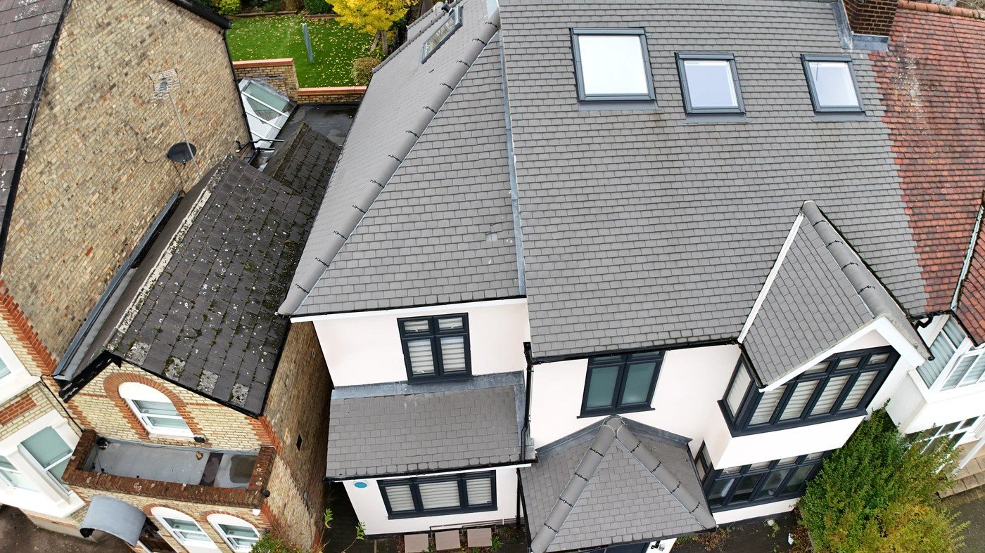
The adjacent property’s original pitched roof (visible to the left in the aerial imagery) shows extensive lichen and moss colonisation across the full tile field, including the ridge, hip, and general slopes. Whilst this roof falls outside the direct scope of the survey, its condition is noted as it represents the trajectory the surveyed property’s tile elements will follow if moss is not managed proactively.
On the surveyed property itself, early-stage moss growth is identified on the lower courses of the swept hip tiles (Section 3.6) and at several tile-to-flat-roof junctions. Moss spores are widespread in the urban North London environment and once established, growth accelerates rapidly on north- and east-facing surfaces.
Potential Consequences if Unaddressed
- Moss root systems penetrate tile and slate surfaces, holding moisture against the material and accelerating frost-spalling of the tile face.
- Moss colonies trap airborne debris and leaf litter, forming a mat that directs water towards joints and junctions rather than allowing it to drain freely across the tile surface.
- At valley and hip junctions, moss build-up can cause water to back up behind blockages, potentially overtopping into the roof void.
Recommended Remedial Works
- Apply a proprietary biocide moss treatment (e.g. Moss Clear Pro or equivalent) to all affected tile surfaces in accordance with the manufacturer’s instructions and Environment Agency guidance on run-off management; allow the treatment to kill the moss in situ before brushing off.
- Once clear, fit a zinc or copper moss-inhibiting strip at the ridge — rainwater washing over the metallic strip creates a dilute ion solution that inhibits future moss establishment.
- Repeat biocide treatment at the recommended interval (typically 2–3 years in an urban environment).
Flat Roof Drainage Staining — Neighbouring & Extension Roofs
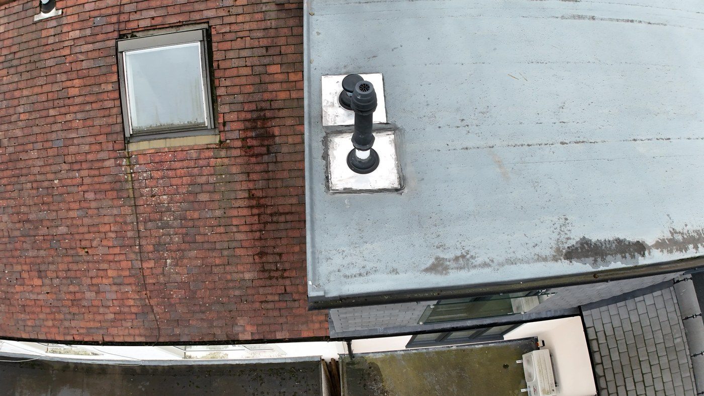
The wider survey imagery reveals evidence of significant water staining and algae growth on adjacent flat roof surfaces visible within the drone’s field of view. The staining patterns — characterised by dark algae trails and tide-mark residue — are consistent with recurrent ponding, where water is retained on the roof surface for extended periods before evaporating, leaving behind algae colonies and mineral deposits.
Where these flat roofs relate to sections of the surveyed property or its outbuildings, the condition should be considered in the context of the overall drainage strategy. Where they relate to immediately adjacent properties, the observation is noted for completeness as water run-off from neighbouring poorly-drained flat roofs can contribute to boundary wall saturation and moisture issues at party wall junctions.
Recommended Action
- Identify which of the stained flat roof sections fall within the property boundary and engage a flat roofing specialist to assess falls and drainage provision.
- Ensure all outlets, hoppers, and downpipes serving these sections are clear and functioning.
- Where algae staining is found on sections within the property, consider a biocide wash followed by inspection of the membrane condition — algae growth on mineral-surfaced felt can mask blistering and lap joint failures.
Findings & Action Schedule
The following table summarises all defects identified during the drone inspection, in priority order. Defects graded D or E should be addressed without undue delay. Defects graded C are recommended for inclusion in the next planned maintenance programme.
| No. | Defect | Location | Grade | Action |
|---|---|---|---|---|
| 1 | Ponding water on flat felt roof | Dormer flat roof deck | D | Within 3–6 months |
| 2 | Lead flashing not dressed at abutment | Dormer wall/roof junction | D | Within 3–6 months |
| 3 | Chimney stack — vegetation & failed flaunching | Chimney head | D | Within 3–6 months |
| 4 | Slipped tile on main pitched roof | Front elevation pitch | D | Within 3–6 months |
| 5 | Poor cement mortar to tile verge | Tile-to-wall junction | C | Within 12 months |
| 6 | Hip tile foam filler at eaves | Swept hip eaves junction | C | Within 12 months |
| 7 | Moss growth on hip tiles | Lower hip courses | C | Within 12 months |
| 8 | Flat roof surface staining — adjacent sections | Outbuilding / extension roofs | C | Monitor / investigate |
Overall Roof Condition Grade
Poor — multiple defects requiring attention
The property presents with four Grade D defects (ponding on flat roof, undressed lead flashing, chimney vegetation, and slipped tile) alongside a further four Grade C observations. The four Grade D defects represent active water ingress risks and should be programmed for remediation without delay, ideally within a single combined works package to reduce access costs. The Grade C items should be addressed within the following twelve months.
Get your own report
Ready to see what’s on your roof?
You’ll receive the same format — graded findings, annotated photos, recommended remedial works, and a full action schedule — for your property.
Disclaimer & Limitations
This report has been prepared by North London Drone Surveys for the sole use of the instructing party named on the cover sheet. It must not be reproduced, disclosed, or relied upon by any third party without the prior written consent of North London Drone Surveys. The report is based on a visual-only inspection conducted by unmanned aerial vehicle on the date stated. No physical access was made to the roof surface, roof void, or internal fabric of the building during this survey.
Findings and recommendations reflect the professional opinion of the operator based on observed imagery. They do not constitute a specification for works, a structural assessment, or a warranty as to the condition of any element not directly visible from the air. Defects concealed beneath roof coverings, within wall cavities, or requiring physical probing cannot be identified by UAV inspection. Where this report recommends further investigation by a specialist contractor, those works should be completed before any detailed remedial specification is agreed.
All drone operations were conducted in compliance with UK CAA Regulation (EU) 2019/947 as retained in UK law, the Air Navigation Order 2016, and within the operator’s valid commercial permissions. The operator holds Public Liability Insurance appropriate for commercial UAV operations.
North London Drone Surveys
CAA GVC-Qualified Commercial UAV Operator
End of Report · NLDS-2025-1000